|
 |
| Norm Voelzow |
|
|
 |
| ALI 3.710USB Rotalign® Pro PC Simulation Program (click) |
|
|
Spacer
Shaft Tolerances Explained
___________________________________________________________
|
Question:
From Sim Sze Tung – Singapore China. The tolerance card for spacer shaft
is in mils/inch. Does this per inch refer to spacer shaft length or coupling
diameter and, is this a gap or offset reading?
Explanation:
Spacer
Shaft Tolerances
To apply Alignment Tolerances to a Spacer Shaft
(Jackshaft, Spoolpiece etc.) we multiply the length of the Spacer Shaft in
inches times the speed related Spacer Shaft tolerance from the tolerance table
shown below. This will give us a tolerance to be used to check against the
actual offsets, both vertical and horizontal,
that the Optalign® or Rotalign® will show us at each coupling center
in the Coupling Mode. Note: Offset is the amount
the two centerlines are separated
(offset) from each other at any specified point. Normally, offset is measured
at the center of the coupling(s) which is where
the torque is transmitted. Typically we express alignment related offsets
as VO for Vertical Offset and HO
for Horizontal Offset.
For
example, using a 60" Spacer Shaft which
rotates at 1,800 RPM, we multiply the Spacer
Shaft Length of 60" by the speed related Spacer Shaft tolerance
of 0.6 mils/in. which results in an offset tolerance
of 36 mils. This tolerance will be used to check
the actual offset the Optalign® or Rotalign® will show us in the Coupling
Mode and must be checked at each coupling center!
|
 |
| Tolerance Table (click) |
|
|
The
Optalign® or Rotalign® calculates the
actual offset between the Stationary Machine
and M.T.B.M. (Machine To Be Moved) centerlines,
using the dimensions you entered. Also, the Optalign® or Rotalign®
can show us the relationship or offset between Stationary Machine and M.T.B.M.
centerlines anywhere along these centerlines.
Even if you are using the older Optalign® IR (invisible beam) or V system
you can still compare two points or both ends of the Spacer Shaft as shown
below! (Note: To do this with the older Optalign®
IR / V we need to change the dimension from Prism to Coupling Center
after getting the results for the one end!)
|
You
can see from this example illustrating the actual Vertical
Offsets that by checking the tolerance at both coupling centers and
correcting the alignment, we are actually controlling
the angularity between the two machines
centerlines and possibly preventing a catastrophic
failure! With Spacer Shafts we do not
need to look at both Gap and Offset as we do with Short Coupled machines since
once we achieve Tolerance on a Spacer Shaft alignment the angularity will
be very small and well below Tolerance.
Note
1: For Spacer Shafts under 6" in length, we would use the Short
Coupled Tolerances which are found under the headings of Gap and Offset in
the tolerance table shown above.
Note
2: Use OEM or in-house tolerances if available.
Have
a Grand Day!
Norm & Bev Voelzow • Voelzow & Company, Inc,
©
Copyright 1997 Voelzow & Company, Inc. Wingate, North Carolina
|
Two
Commonly Asked Soft Foot Questions
___________________________________________________________
|
Question
#1: What does the Optalign® or Rotalign® show us in the Soft
Foot mode?
Answer: Shaft movement
only — not foot movement and
not soft foot correction!
Question
#2: Why doesn't the Optalign® or Rotalign® show the actual
Soft Foot correction?
Short
Answer: They are not designed to!
Long
Answer: We do not enter a dimension from the base to the centerline
of the motor shaft nor do we enter an inside dimension (side to side) of the
feet! In order for any computer to "guess" at the actual soft foot
fix, the computer would need the front to back foot dimension plus these additional
dimensions. Notice I said "guess"!
How many times do we have perfectly flat feet and a perfectly flat base —
never or almost never! If we want a computer to calculate the soft
foot correction — we would need to supply the motor front to back foot
dimension, the dimensions mentioned above and the following information:
- Is
the foot flat or bent? If bent, is it bent up or down — towards the
outside of the motor;
is it bent up or down — towards the front or back of the motor; or
a combination of both?
- Is
the base warped? If warped — which way?
- Is
the base solid or corroded or flimsy?
- Are
you using a stack of shims, a few shims or no shims when measuring soft
foot?
-
Are the shims bent? Are the shims dirty?
-
Is there dirt under the motor feet?
-
Etcetera, Etcetera, Etcetera !!!
Get
the picture? That is a lot of information to try to get just to
have a computer still "guess" at our
Soft Foot correction! We recommend that you work on the foot that the Optalign®
or Rotalign® displayed as having the most movement — using
feeler gages! Fix that foot and recheck
all of them again! (Some use shim stock to determine the correction but may
not notice the taper!)
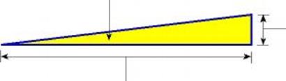
Here
is another picture for you. This triangle graphically shows you how the Optalign®
or Rotalign® is calculating the movement of the shaft centerline. The
base of the triangle is where the motor centerline is with the all of the
feet tight. The Hypotenuse is the motor centerline with one foot loose! Interesting
— I think so!
|
This
is the Angle measured by the Optalign®,
Masterlign® or Rotalign®.
|
| This
is the number displayed on the Optalign®, Masterlign®
or Rotalign® screen which is Shaft Movement
at the shaft centerline and NOT Soft Foot shim correction!
|
This
is the Front to Back foot dimension entered
by you in the Optalign®, Masterlign® or Rotalign® dimension
screen.
|
The
number displayed on the Optalign® or Rotalign® screen in the soft
foot mode is based upon a movement of the shaft — PERIOD!
Again; Shaft movement only — not
foot movement and not soft foot correction!
Go to the foot with the most movement and use feeler gages to determine the
correction. With feeler gages you can also determine if there is any taper
indicating a bent foot. Bent feet or rolled/bowed bases usually require step
shimming. Don't try to short cut by "side stepping" soft foot! There
are no short cuts with soft foot — just perseverance, determination
and finally skill! Good Luck, Norm Voelzow
©
Copyright 1997 Voelzow & Company, Inc. Wingate, North Carolina
Optalign®
& Rotalign® are registered trademarks of Prüftechnik Dieter Bush
AG of Ismaning, Germany
|
___________________________________________________________
|
We
have written the above Laser Tip about Soft Foot
because checking Soft Foot with a laser is so
misunderstood by so many people!
We have explained what the laser "sees"
in the Soft Foot mode since 1986, shown 1,000's of people in classes and in
the field and we turn around and people go back to assuming
the lasers show the Soft Foot shim correction!
Go figure!
Do
yourself a favor and don't complicate
Soft Foot! Use the laser to ferret
out the problem foot or feet and then use your head and a set of feeler gages
to "really see" exactly what is going
on under that foot!
Remember,
I never said that doing Alignment or correcting
Soft Foot was easy with the laser but I always
have said that a laser made both much easier!
Note:
This Laser Tip is two - sided with the Typical Causes
Of Soft Foot graphics by Bev Voelzow shown on the reverse side! You
will need to click on the "Two Commonly Asked Soft
Foot Questions" PDF icon above to see Bev's work!
Have
a Grand Day!
Norm & Bev Voelzow • Voelzow & Company, Inc,
©
Copyright 1997 Voelzow & Company, Inc. Wingate, North Carolina
|
Recent
Laser Tips for Download
___________________________________________________________
|
___________________________________________________________
|
|
|
 |
| In the USA - Need a Calibration Check? (CLICK) |
|
|
|
Compact
Chain Tool
___________________________________________________________
|
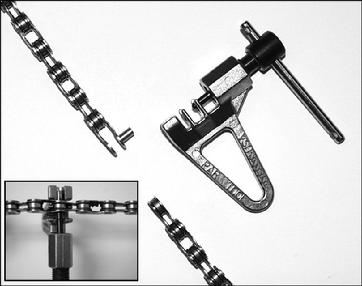 |
| VCT-5 Compact Chain Tool - (click) |
|
|
The
VCT-5 Compact Chain Tool facilitates shortening
or lengthening bracket chain without damaging the existing chain or special
ends!
VCT-5
Compact Chain Tool . . $21.00 each
(Chain
not included)
VCT-5
set Compact Chain Tool w/ two 30" lengths of extra chain . .
$45.00 per set
Important:
Do not insert the extra chain needed by taking apart the installed master link(s)
but, using the VCT-5 Compact Chain Tool, skip over
a link or so from the master link and
insert at that point. Most of us will break the lightweight European master
link – especially Norm Voelzow (me)!
We
accept, Master Card and Visa! Call 704-233-9222 or request
a Quotation by email.
|

VCT-5 Compact Chain Tool Flier |
Sunlight
and The Lasers
___________________________________________________________
|
Sunlight
and The Lasers
Occasionally
we have had customers tell us that they thought that Sunlight
was preventing the laser system from taking measurements when the machinery
being aligned was located outdoors and that they
wanted a more powerful laser! We explained that a more powerful laser is not
the answer but in fact they were getting interference from direct Sunlight
or too much reflected light off of other equipment!
Even
though all of the Pruftechnik laser systems filter out all light except for
670nm frequency used
by the Rotalign and Optalign
lasers – the Sun generates all of the frequencies
of light! Another important point is the fact that the Rotalign and Optalign
lasers power are designed and rated as Class 2 lasers - for Safety
reasons!
Even
if the factory went to the next class laser, Class 3, you can still can experience
the direct or reflected Sunlight issue as the photocell
in the Rotalign Receiver or Optalign Transducer will still see a lot of the
lasers 670nm frequency from the Sunlight.
Important: Anything above a Class 3 laser could not
be used in the open because of the chance of an individual being blinded.
Here's
another way to look at the Sunlight issue. Imagine
that you were using a camera mounted where the laser's Receiver or Transducer
is and were trying to take a picture of the other component with the Sun
in the background. . . . . ! You would have the same problem with the
Sunlight unless you had a hood on your camera's
lens – get the picture!
When
doing alignment outdoors you most probably will need to use a Sunshade!
But, not just anything you have laying around as you must be careful not to
put any excessive weight on the Rotalign Receiver or Optalign Transducer –
and that is why the older Sunshade we had previously
was so light but fragile!
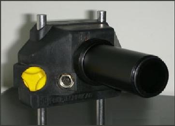
In order to overcome this inconvenience and fragility the US Pruftechnik Distributor,
Ludeca, developed the L 660 Sunshade which helps
the user to overcome the Sunlight issue outdoors
during the initial set-up and when measuring! Much like a camera with the attached
hood used on large diameter lenses – this Sunshade
is designed for Rotalign style Receivers and Optalign style Transducers as shown
in the photos to the right.
If
you are using your laser system outdoors we recommend you get a Sunshade!
You can order an L 660 Sunshade from Nils
Heilemann at Ludeca (305-591-8935) – please tell Nils that
Norm and Bev said hello - thanks!
|
 |
| L660 Sunshade mounted on a Rotalign Receiver (click) |
|
|
 |
| L660 Sunshade mounted on an Optalign Plus / smartALIGN Transducer (click) |
|
|
___________________________________________________________
|
Hello,
If
you want more information, wish to comment on a Laser
Tip, request that a Laser Tip be made
or request a previous Tip - please
use the Request Form link below, call us at 704-233-9222 or send
us an email.
Thanks
- Norm & Bev
Laser
Tips © Copyright 1997 Voelzow & Company, Inc. Wingate, North Carolina
|
_____________________________________________________________________
Links
The
following are some very good links for you to visit and well worth your time!
Just click on the graphic and be sure to check back as more great links will
be added very soon. Norm
_____________________________________________________________________
|
|
 |
| We ship daily by the Big Brown truck on orders received as late as 5:30 pm EST! |
|
|
|
Untitled Document
© Copyright Voelzow & Company, Inc. - Wingate, North Carolina USA.
Reference
the Digital Millennium Copyright Act Of 1998.
Top
Gun®, when used with Laser Shaft Alignment, is a registered trademark
of Voelzow & Company, Inc Wingate, North Carolina USA.
Note:
We have not given anyone or any company
permission to use any text from our website on their website or in printed material!
|
 |
| Send E-mail |
|
| |
|
Top
of Page
___________________________________________________________
|
|